Description:
A very high quality intercom, which may also be used for room monitoring.
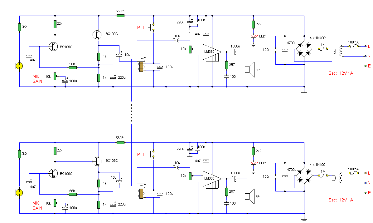
Circuit diagram
Notes:
This circuit consists of two identical intercom units. Each unit contains a power supply, microphone preamplifier, audio amplifier and a Push To Talk (PTT) relay circuit. Only 2 wires are required to connect the units together. Due to the low output impedance of the mic preamp, screened cable is not necessary and ordinary 2 core speaker cable, or bell wire may be used.
The schematic can be broken into 34 parts, power supply, mic preamp, audio amplifierand PTT circuit. The power supply is designed to be left on all the time, which is why no on / off switch is provided. A standard 12 V RMS secondary transformer of 12VA will power the unit. Fuses are provided at the primary input and also secondary, before the rectifier. The 1 A fuse needs to be a slow blow type as it has to handle the peak rectifier current as the power supply electrolytics charge from zero volts.
The microphone amplifier is a 2 transistor direct coupled amplifier. BC108B transistors will work equally well in place of the BC109C transistors. The microphone used is a 3 terminal electret condenser microphone insert. These are popular and require a small current to operate. The preamp is shown in my audio circuit section as well, but has a very high gain and low distortion. The last transistor is biased to around half the supply voltage; this provides the maximum overload margin for loud signals or loud voices. The gain may be adjusted with the 10k preset. Sensitivity is very high, and a ticking clock can easily be heard from the distant loudspeaker.
The amplifier is based on the popular National Semiconductor LM380. A 50 mV input is all thats required to deliver 2W RMS into an 8 ohm loudspeaker. The choice of loudspeaker determines overall sound quality. A small loudspeaker may not produce a lot of bass, I used an old 8 inch radio loudspeaker. The 4.7u capacitor at pin 1 of the LM380 helps filter out any mains hum on the power supply. This can be increased to a 10u capacitor for better power supply rejection ratio.
The push to talk (PTT) circuit is very simple. A SPDT relay is used to switch between mic preamplifier output or loudspeaker input. The normally closed contact is set so that each intercom unit is "listening". The non latching push button switch must be held to talk. The 100u capacitor across the relay has two functions. It prevents the relays back emf from destroying the semiconductors, and also delays the release of the relay. This delay is deliberate, and prevents any last word from being "chopped" off.
Setting Up and Testing:
This circuit does not include a "call" button. This is simply because it is designed to be left on all the time, someone speaking from one unit will be heard in the other, and vice versa. Setup is simple, set to volume to a comfortable level, and adjust the mic preset while speaking with "normal volume" from one meter away. You do not need to be in close contact with the microphone, it will pick up a conversation from anywhere in a room. If the units are a long way away, there is a tendency for the cable to pick up hum, or radio interference. There are various defenses against this. One way is to use a twisted pair cable, each successive turn cancels the interference from the turn before. Another method is to use a small capacitor of say 100n between the common terminal of each relay and ground. This shunts high frequency signals to earth. Another method is to use a low value resistor of about 1k. This will shunt interference and hum, but will shunt the speech signal as well. However as the output impedance of each mic preamp is low, and the speech signals are also low, this will have little effect on speech but reduce interference to an acceptable level.
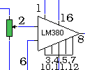
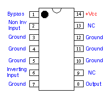
IC Pinout:
The LM380 pinout viewed from above is shown below on the left. In the schematic, the LM380 has been represented as a triangle, the pins are shown on the right hand diagram. Pins marked "NC" have no connection and are not used.

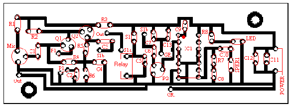
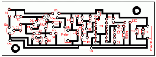
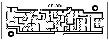
PCB Layout:
Corey Rametta has kindly drafted a PCB layout for this project. First an oversized version to show component placement. Note the tracks on the bottom side, components on the top side.
Below is the actual size version shown track side.
author: Andy Collinson
e-mail: anc@mitedu.freeserve.co.uk
web site: http://www.zen22142.zen.co.uk
 Audio (49)