Electronic projects |
|
|
|
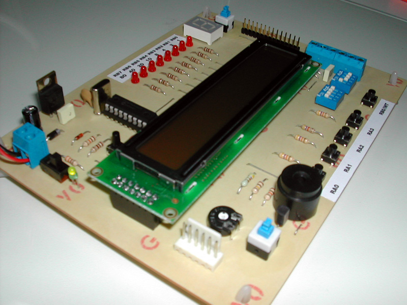
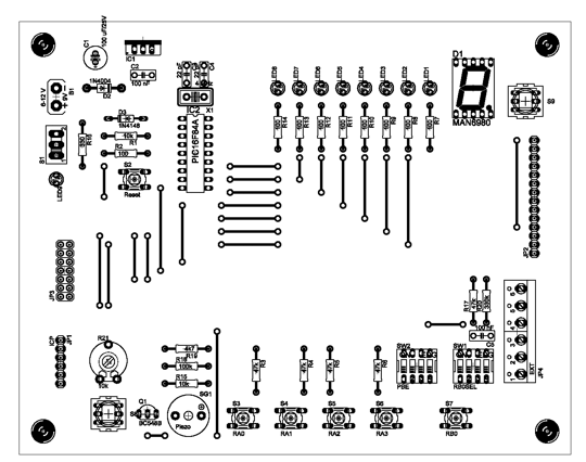
PlayPIC®This is a new design of a tutorial board based on the popular PIC16F84A microcontroller. It features eight single leds, a 7-segment display, an LCD display and five push buttons. It is an ideal solution for the beginner to take his/her first programming steps in the world of microcontrollers. Having an in-circuit-programming (ICP) header, it can be easily reprogrammed without unplugging the microcontroller each time, provided that the programmer also supports this feature (like OziPic’er). Circuit diagram Connections PIC16F84A.......................Feature
Feature Description
The top photo shows the in-circuit-programming procedure with the help of an appropriate programmer (like OziPic'er) which features an ICP header. In order for the procedure to work correctly, the LCD module has to be disconnected from its socket during programming. Any futher ideas, comments and corrections are mostly welcome to billy@ee.auth.gr
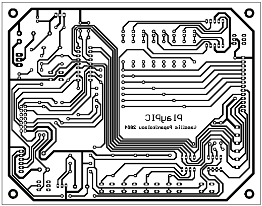
Download Schematic, PCB, silkscreen e-mail: billy@ee.auth.gr web site: http://www.electronics-lab.com |
 Audio (49) Power & high voltage (43) Radio (23) Light & LED (31) Tools & measurement (40) Telephone (18) Automotive (10) Microcontrollers (12) Sensors & control (47) Timers & oscillators (40) Miscellaneous (26) Audio (49) Power & high voltage (43) Radio (23) Light & LED (31) Tools & measurement (40) Telephone (18) Automotive (10) Microcontrollers (12) Sensors & control (47) Timers & oscillators (40) Miscellaneous (26)All subcategories microcontrollers "SimpleMouse" Smartcardprogrammer ATMEL 89 Series Flash Microcontroller EPROM adapter for ATMEL 89 Series Flash Microcontroller Programmer Ver 2.0 Funcard Programmer by Diesel Gold wafer cards iButton electronic lock Phoenix Programmer PIC diode tester Ponyprog Circuit for ATMEL'S AVR Ponyprog Circuit for AVR & PIC16F84 Doorbell for the Deaf High Quality Intercom Combinational Conjuring Trick POT-PLANT POWER Ultrasonic Dog Whistle Quiz Circuit LED Torch Insect Repellant Speaker Microphone Circuit Magic Wand Conjuring Trick. Led display digital Voltmeter 500W low cost 12V to 220V inverter Low pass filter - Subwoofer Metal Detector High And Low Voltage Cut Off With Time Delay 2N3055 Power Amplifier Basic UPS Power Supply 200W audio amplifier LED Torch 100W RMS Amplifier DIY Electronics Projects Promote Your Page Too |