Electronic projects


you are here: home page :: projects :: Power & high voltage :: other :: Receiver Battery Low Voltage Alarm

Receiver Battery Low Voltage Alarm

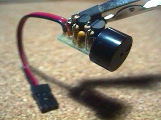
Here is another equally cool low voltage alarm circuit for your glider receiver battery that I've shamelessly stolen from George Steiner's book "A to Z--Radio Control Electronic Journal" (see below). I've modified it to use with small battery packs in R/C gliders. This design has a trigger voltage at about 4.3 volts, and it draws 1mA or less when quiet and about 4mA when buzzing. This can be constructed from parts fromt Radio Shack, though you may need to order a few through them.
The voltage of a receiver system is punctuated by low-voltage spikes every time the servo motors spin up, since the servos draw more than the battery can deliver. With large receiver battery packs, this is not as much of an issue, and it may not be noticeable. However with 270mA and smaller battery packs, particularly with more than two servos, low voltage alarms can chirp constantly, every time a servo moves. The challenge is to design in a little slack or delay, just enough so that you are not annoyed by constant chirping, but not too much so that the chirps can give you a warning before the battery is completely exhausted. Here, this "hysteresis" is adjusted with the capacitor. For large packs (600mA and above), no capacitor is probably needed, although I've been using a 1uF capacitor on my open class ship with 6 servos and a 600mA battery. For 270 mA and two servos, I'd suggest trying a 1uF capacitor. For 150mA or less, a 2.2uF capacitor works well. If you want to know only when the battery has finally reached the trigger voltage, try a 5uF (or 4.7uF) capacitor. The actual type of capacitor is not critical, but tantalum capacitors are physically smaller. If you want to worry about the polarity of the capacitor, the negative side should be directed toward the negative pole of the battery, but at these relatively low voltages compared to the capacitor rating, the polarity probably does not matter.
This circuit is set up for a four cell receiver battery pack at a trigger voltage of about 4.3 volts (about 1.1volts/cell). You can adjust R1 (here a 3.3k resistor) to change the trigger voltage of the circuit. For example, for a 5 cell pack, to change the trigger voltage to 5.5 volts, change R1 to 2.2k. For a three cell pack, to change the trigger voltage to 3.3 volts, change R1 to 6.8 k (or use two 3.3k resistors in parallel by soldering a resistor in each hole and twisting together the top leads). Because of slight variability in tolerances of the componants, you should check this little device with a variable power source and a voltmeter to confirm its trigger point. Alternately, use your digital voltmeter or expanded scale voltmeter to calibrate its chirp pattern by measuring the voltage of the onboard battery pack intermittently as you fly.
Make sure the band on the Zener diode is toward the "+" side (toward R1). Solder a battery connector or servo connector to the board with positive and negative as shown, and plug the connector into an unused slot in your receiver.

Circuit diagram

Radio Shack parts: Here again, you can use smaller rated resistors if you can get them--1/8 watt or less is fine. Tantalum capacitors are physically smaller, but any composition will work.
273-074 Miniature Piezo Buzzer, 12v, PC board mount
271-312 1/4 watt 5% carbon film resistors, 500 pieces (Take the plunge!)
276-1604 Package of 15 PNP small signal 2N3906-type transistors. Could use instead 276-2016 $0.59 2N3904 PNP transistors
RSU 11673505 3.3v Zener diode (not on shelf--need to order 1-800-THE-SHACK)
272-1434 1uf tantalum capacitor (see above for choice of capacitor)
RSU 11295888 2.2uF tantalum capacitor (not on shelf--need to order)
272-1024 4.7uF radial-lead electrolytic capacitor

Digikey (1-800-344-4539) part numbers: Digikey does sell the peizo buzzers, but they are much more expensive than those at Radio Shack and are larger as well.
2N3906-ND PNP general purpose amp/switch transistor
1N5226BMSCT-ND 3.3v Zener diode 500mA
3.3KEBK-ND 1/8 watt resistors
4.7KEBK-ND 1/8 watt resistors
10KEBK-ND 1/8 watt resistors
P2105-ND 1.0uF Tantalum capacitor 16volt
P2022-ND 2.2uF Tantalum capacitor 10volt
P2024-ND 4.7uF Tantalum capacitor 10 volt
FP012C-5-ND 3M clear 0.5" heat shrink tubing, 5 feet

George Steiner's book, crammed with cool R/C radio info, can be had for $19.95 postage paid from the following:
GSP AZ Journal
2238 Rogue River Drive
Sacramento CA 95826
phone: 916-362-1962

author: Rob Crockett 10/99
e-mail:
web site: http://www.electronics-lab.com
project categories:
folder Audio (49)
folder Power & high voltage (43)
folder Radio (23)
folder Light & LED (31)
folder Tools & measurement (40)
folder Telephone (18)
folder Automotive (10)
folder Microcontrollers (12)
folder Sensors & control (47)
folder Timers & oscillators (40)
folder Miscellaneous (26)

StumbleUpon button

Share this page
Bookmark and Share
project subcategories:
All subcategories
power supplies
battery chargers
high voltage
inverters
free energy
other

similar projects:
Fuse Monitor / Alarm
High And Low Voltage Cut Off With Time Delay
Low Voltage Alarm
Precision Receiver Battery Low Voltage Alarm
Pulse Width Modulation DC Motor Control
Self-powered Fast Battery-Tester
Solid State Power Controller
Voltage follower with 1G ohm input resistance
Voltage Monitor

recently added projects:
Doorbell for the Deaf
High Quality Intercom
Combinational Conjuring Trick
POT-PLANT POWER
Ultrasonic Dog Whistle
Quiz Circuit
LED Torch
Insect Repellant
Speaker Microphone Circuit
Magic Wand Conjuring Trick.

most popular projects:
Led display digital Voltmeter
500W low cost 12V to 220V inverter
Low pass filter - Subwoofer
High And Low Voltage Cut Off With Time Delay
Metal Detector
2N3055 Power Amplifier
Basic UPS Power Supply
200W audio amplifier
LED Torch
100W RMS Amplifier


DIY Electronics Projects

Promote Your Page Too