Electronic projects |
|
|
Economy radar detector
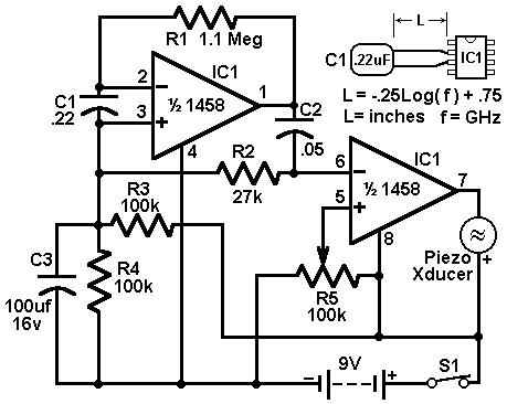
This circuit uses a 1458 dual op-amp to form a radar detector. C1 is the detector of the radar signal. The first op-amp forms a current-to-voltage converter and the second op-amp buffers the output to drive the piezo transducer. R5 sets the switching threshold of the second op-amp; normally it is adjusted so that the circuit barely triggers on background noise, then it's backed off a bit. The response of the circuit may be tuned by adjusting the length of the leads on C1. For typical road-radar systems, the input capacitor's leads should be about 0.5 to 0.6 inches long. author: "Radio-Electronics" Magazine, Jul,86 issue (C) Copyright Gernsback Publications, Inc., 1986 e-mail: web site: http://www.electronics-lab.com
You enjoyed this site?
If so, you might want to consider making a donation to help me to pay for traffic & development tools.
|
Audio (49) Power & high voltage (43) Radio (23) Light & LED (31) Tools & measurement (40) Telephone (18) Automotive (10) Microcontrollers (12) Sensors & control (47) Timers & oscillators (40) Miscellaneous (26) All subcategories Miscellaneous 7 Segment LED Counter Cuckoo sound Generator Digital Step-Km Counter Digital Stopwatch 0-60sec Digital Stopwatch 0-99sec Downed Model Locator Downed Model Locator II Electronic Locker IR Remote Control Jammer Keys Finder Doorbell for the Deaf High Quality Intercom Combinational Conjuring Trick POT-PLANT POWER Ultrasonic Dog Whistle Quiz Circuit LED Torch Insect Repellant Speaker Microphone Circuit Magic Wand Conjuring Trick. 100W RMS Amplifier 500W low cost 12V to 220V inverter 12 Volt 30 Amp PSU 60W Guitar Amplifier 12VDC Fluorescent Lamp Driver 2N3055 Power Amplifier 200W audio amplifier Cellular Phone calling Detector 15W Fm-transmitter 5,000W ultra-light, high-power amplifier, without switching-mode power supply |